

The LilyGO-T-Eth-POE board is not shown in the boards list in the Arduino IDE. You select the ESP32 Dev Board from the boards list.
The T-Eth-POE uses custom libraries. The libraries are found at https://github.com/Xinyuan-LilyGO/LilyGO-T-ETH-Series. These can conflict with other libraries so what I did was create a seperate user account for development for the T-Eth-POE. I then installed the custom libraries into the Arduino directory. This gives me a clean development environment that can't conflict with other libraries.
To use I2C with these ESP32 modules you're likely to need to map some GPIO pins to the I2C bus. These new pin definitions are then passed to the Arduino Wire library begin function in setup. You must take care to use pins that are I/O rather than Input only. Check the datasheet. Pins 21/22 are the Arduino default for SDA/SCL I2C, but the POE board doesn't break out those pins.
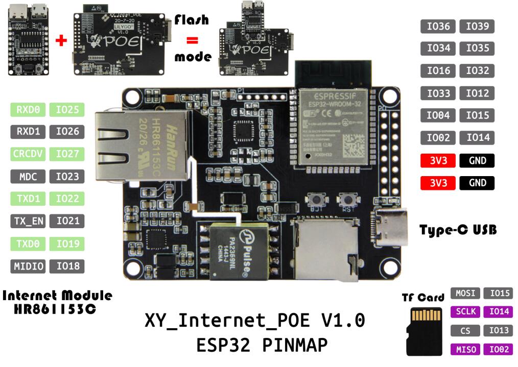
For example, on the POE board the expansion connector is:
| Pin | Function | Pin | Function |
|---|---|---|---|
| 36 | Input | 39 | Input |
| 34 | Input | 35 | Input |
| 16 | Input/Output | 32 | Input/Output |
| 33 | Input/Output | 12 | Input/Output |
| 04 | Input/Output | 15 | MOSI |
| 02 | MISO | 14 | SCLK |
So to use I2C we must select two pins and pass that to the Wire library. We can't use the top four pins (36,39,34,35) because they're input only. There are three pins used for SPI (02,14,15) so they're also not available. Any of the remaining pins can be used (16,32,33,12,04).
The code would include something like this:
#include <Wire.h>

// Pins used for i2c
#define I2C_SDA 33
#define I2C_SCL 32

void setup()
{
  Wire.begin(I2C_SDA,I2C_SCL);
}