
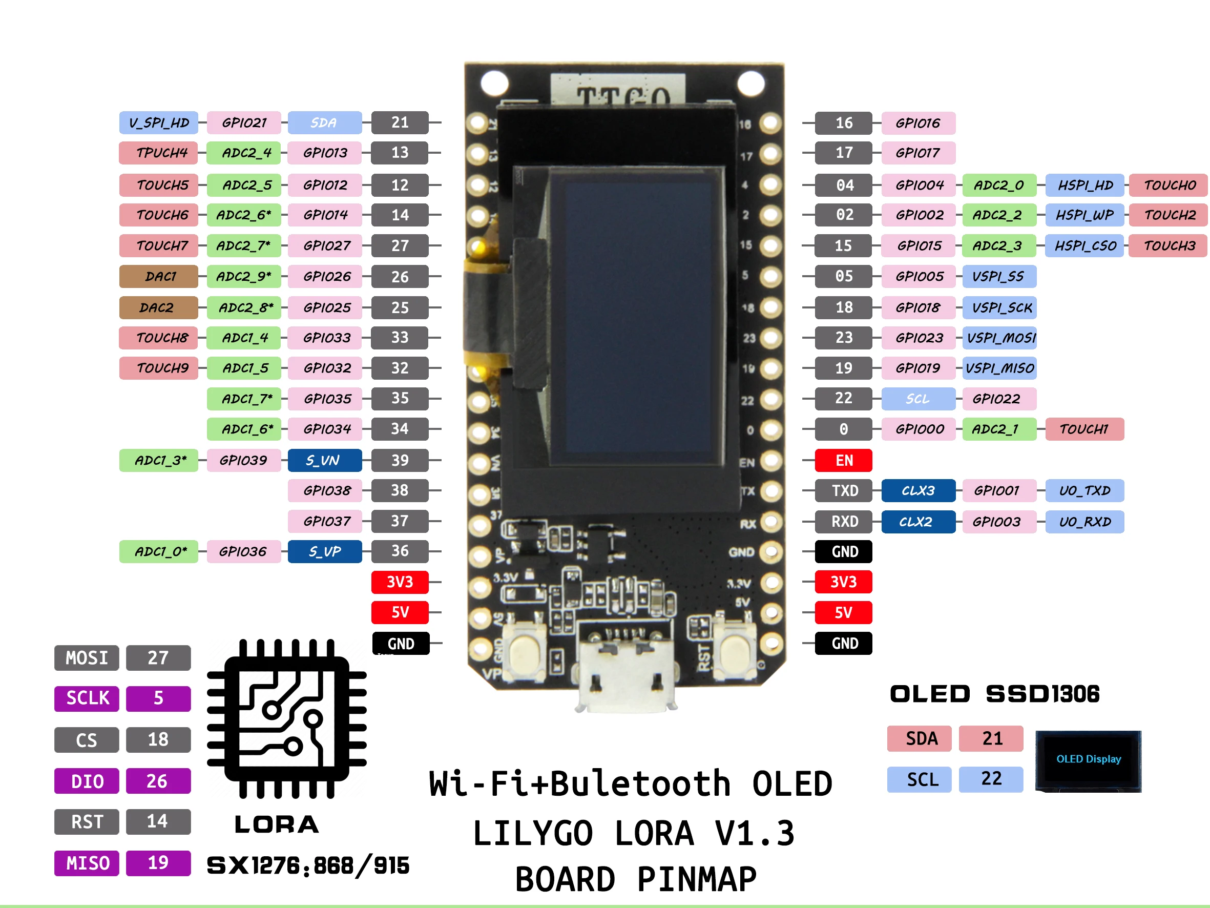
Arduino IDE has a board type for 'TTGO Lora32-OLED'
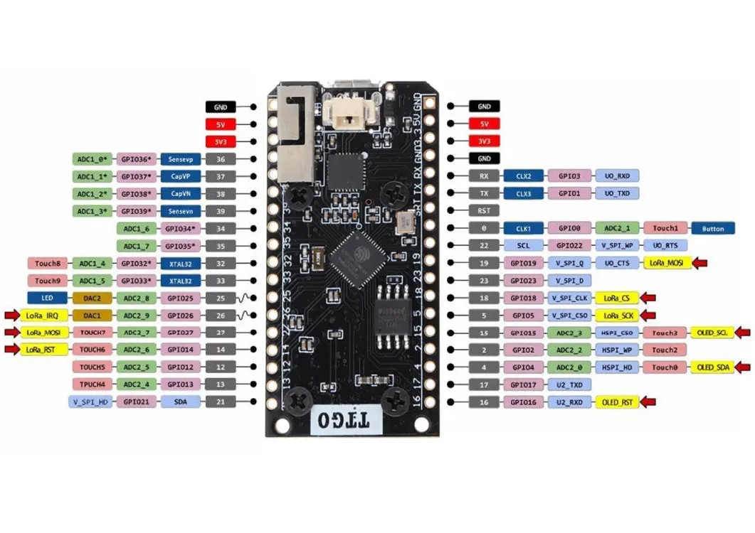
To use LoRa, we need to set the pin definitions to match. The same applies to the OLED I2C.
#include <SPI.h>
#include <LoRa.h>
#include <U8x8lib.h>
#include <Wire.h>

U8X8_SSD1306_128X64_NONAME_HW_I2C u8x8(16);

const int csPin = 18;          // LoRa radio chip select
const int resetPin = 14;       // LoRa radio reset
const int irqPin = 26;         // must be a hardware interrupt pin

#define SDA 4
#define SCL 15

void setup() {
  LoRa.setPins(csPin, resetPin, irqPin);
  Wire.begin(SDA,SCL);
  u8x8.begin();
  u8x8.setPowerSave(0);
  u8x8.setFont(u8x8_font_chroma48medium8_r);
}
To use the hardware UARTs in the ESP32 you can remap them to any suitable GPIO pins. They do need to be input/output though. On the LoRa32 I've used pins 12 and 13 as they are suitable. Serial is already used for the USB, and Serial1 may be used for internal stuff, so I used Serial2 as the easiest option.
#define RXD2 13
#define TXD2 12
void setup()
{
  Serial2.begin(9600, SERIAL_8N1, RXD2, TXD2);
}
Some example sketches showing this at work. While messing around getting communication going between two ESP32 boards I used my phone to test connection. Then I remembered that XCSoar was installed, which can accept GPS input over bluetooth serial (or UDP). A quick check showed a simple serial to bluetooth worked just fine.
XCSoar supports UDP as well, so I tried that. It is a bit more complicated as you need to assemble each NMEA sentence and send it in a single UDP packet.